
modified: Friday 5 June 2026
author: Hales
markup: textile
Diodes part 1: Homemade copper diodes
Edit 2020-01-05: I now believe this page has incorrect interpretations & conclusions. The water-drop-and-candle method does not seem to be necessary or important for getting non-linear VI curves.
I have discovered it is possible to get similar junction curves using only graphite and various (non-intentionally oxidised) metal surfaces. Ie if you use the octopus circuit described on this page, a graphite pacer lead and a piece of steel (or exposed metal on your test equipment) then it should be possible to observe similar effects.
In retrospect, it would have been a good idea to include some control tests on simpler metal samples in this experiment.
On the weekend I played around trying to make copper-oxide diodes. I succeeded in making something diode-like, but it behaved more like two opposite-facing diodes in parallel. In the rest of this post I’ll detail how I made my ‘un-odes’ and their test results in the hope of encouraging other people to tinker with home-made semiconductors.
I’ve always wanted to make my own semiconductors. My dream is make N and P doped pastes that you can ‘paint’ or ‘dab’ onto bare PCBs to make diode circuits. In some ways this would truly be making my own chips, and it could be expanded to make more complex designs with printing or stencilling. Dreams :)
I have had little luck following many diode-making guides on the web. Often these are aimed toward making one-off diodes for crystal radios. Everything I have read and tried so far has involved hit-and-miss procedures where you hope to make or find a single tiny dot of semiconducting material on a large surface. I want something more reliable.
First Attempts
My motivation was resurrected after reading a page on making copper rectifiers by H.P Friedrichs. He details some of his own attempts at making them. Just like many other guides however he focuses on making a ‘one off’ that gets placed inside a complicated jig to keep contact on a single point of his creation.
Friedrichs uses borax and heat to create a layer of semiconducting cuprous oxide on the surface of a copper fitting. To clean off layers of unwanted cupric oxide he uses an acid. He uses a piece of (lead-tin) solder wire touching the cuprous oxide as the other half of his junction.
I didn’t have have borax handy and being too lazy to walk down the street I decided to keep researching other methods of making cuprous oxide. A Russian video I found suggested I needed to keep a piece of copper accurately at 1000 degrees celsius for extended periods of time to build up a good layer. This discouraged me further.
In the end I decided to just have a play around with some copper, candles and various chemicals I had lying around. I tried dipping a small piece of copper in diluted hydrogen peroxide and boiling it off repeatedly. I tried slowly heating the copper and probing the resulting rainbow of oxides with pencils and solder. After a day’s work I managed to make a single speck of semiconducting region on my copper that was quickly destroyed from me probing it with a pencil.
In the end I found a better way.
EDIT: Note that my final oxide is a black colour. I am uncertain which type of oxide (or combination of oxides) my final result produced.
Test setup
To test my junctions I used an ‘octopus circuit’ hooked to to my oscilloscope. This let me see the ‘I-V curves’ of what I made.
‘I-V curves’ are just graphs of how much current flows through a part depending on the voltage applied to it. The IV curve of a resistor is just a straight line:

Here you can see that a positive voltage across a resistor makes a positive amount of current flow through it, and visa versa. The line follows ohm’s law: V=IR
A diode has a non-linear IV curve:

(Almost) no current flows for negative voltages but lots of current can flow for positive ones. The point at which the curve suddenly sweeps up is often quoted as 0.7V for a normal silicon diode, however it can be much higher or lower depending on the current levels and particular diode you are using.
Also interesting is the curve of a zener diode:

The negative voltage that the curve suddenly sweeps down is referred to as the ‘reverse breakdown’ voltage. This is generally much larger than the 0.7-ish forward breakdown voltage and is sometimes used as a voltage reference in circuits.
An octopus circuit simply applies a voltage across the part you want to test and provides convenient points to measure voltage and current. I stole the circuit I’m using from a video made by w2aew

I made mine with an ordinary 1/4W 1K resistor, a breadboard and a wound AC power supply:
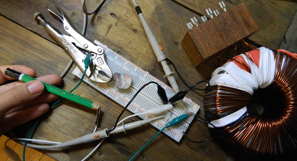
On the right you can see a large toroidal transformer I have had lying on my desk for a while. It outputs 12VAC on each of its secondary windings, which is a bit more than I wanted, so I wound several turns of black wire around it to get about 3VAC. This is an RMS measure so the actual voltage peaks were from about +4.3V to –4.3V.
Make sure you use an isolated power supply (eg a wound transformer)! In this circuit we arbitrarily hook up oscilloscope ground to the middle of the circuit. Please avoid setting fire to anything or harming anyone. Don’t presume something is safe just because you read about it on the internet.
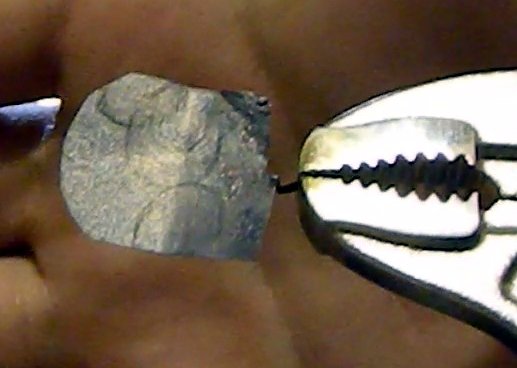
In the picture above I have a small piece of copper being held in vice-grips. One alligator leads connects to the vice-grips and another connects to the end of a pencil. You will want to choose a value of resistor that makes it safe to short these two leads as you will be constantly doing this when hunting for semiconductor junctions.
Make sure the grounded lead is hooked up to the vice-grips (and not the signal lead), otherwise touching the vice-grips with your hand will introduce noise into your signals. You will see a blurry graph on your oscilloscope when this happens.
Not shown in this picture is an analog oscilloscope in X-Y mode. I’m using a Goldstar OS-7040A that my university discarded. She’s an old gal with some some quirks I need to fix, namely:
- her vertical amplification sometimes dies, temporarily revivable with percussive maintenance
- her lower metal housing (’skirt’) keeps falling off during use
- her zero point drifts as she heats up
I thought I fixed the vert-amp problem a couple of years ago by cleaning some contacts, but it’s resurfaced. The temp drift problem is something I had not noticed before — during this experiment the centre of my X-Y graph would slowly move diagonally.
Producing my junctions
Ingredients
- Candle (& method of lighting)
- Small piece of flat copper
- Small pair of vice-grips
- Glass of water
- Toothbrush
- Kitchen scourer
- Scissors
- Misc. parts to make a stand for the vice-grips
Improvise everywhere: no one will have the same parts as me. Lots of things are made of copper. You don’t need vice-grips if you have some wire.
Method
(1) Clean your piece of copper using the scourer. I clean mine on top of a piece of copper PCB rather than directly on my desk so I don’t scrape wood contaminants onto my copper.
(2) Cut a small handle into your piece of copper using your scissors. Make it small and thin so as little heat is lost through it as possible (vice-grips work very well as a heat-sink). Avoid touching the cleaned area of the copper with your fingers.
(3) Light your candle and let it burn for a few minutes so that the flame size stabilises. I had to close my window to get rid of a gentle breeze.
(4) Setup a way of heating the piece of copper above the candle flame. I did this:
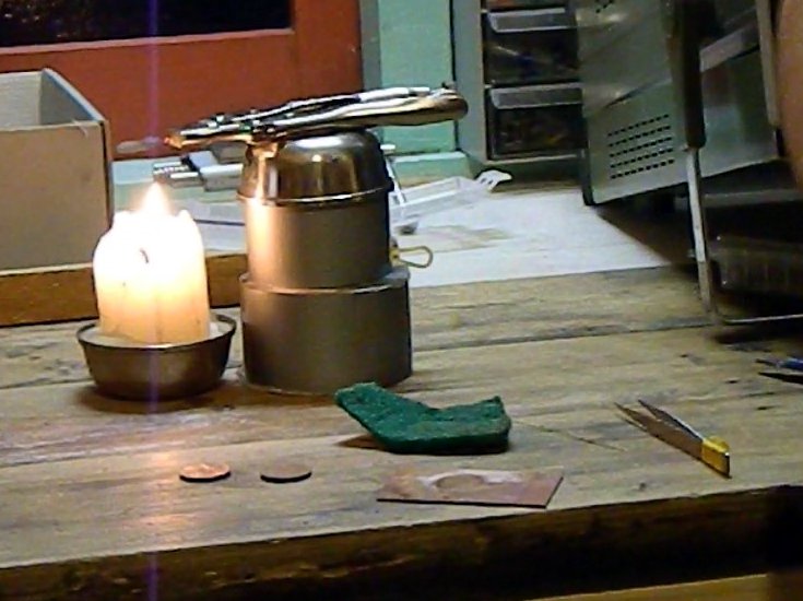
A couple of rolls of tape were acting as a stand for the vice-grips. Atop the rolls of tape was a metal bowl to aid in some heat-sinking, as the vice-grips were getting decently warm in my experiments.
Make sure that the candle flame is not licking your piece of copper or it will start depositing carbon (and smoking).
(5) Keep the copper hot for a few minutes. A nice black layer of corrosion will appear on top:
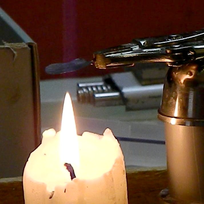
(6) Drip a few drops of water onto the copper one-by-one, with a good time-gap (eg 15 seconds or more) inbetween for the copper to recover its temperature. If the water ‘bounces’ or ‘runs’ off the surface then try again. A successful drop will make some of the darkened surface corrosion ‘rupture’ or ‘move’, temporarily exposing more orange-looking flecks of copper.
(7) Keep the copper heated for a few more minutes. Eventually all the copper on the top surface will again look black, however you may notice some circular patterns from where you placed your drops of water.
(8) Blow out your candle and wait for everything to cool.
(9) Observe what you have made and compare it against what I found. Get angry if it’s not the same and try changing a few of the variables I have been vague about.
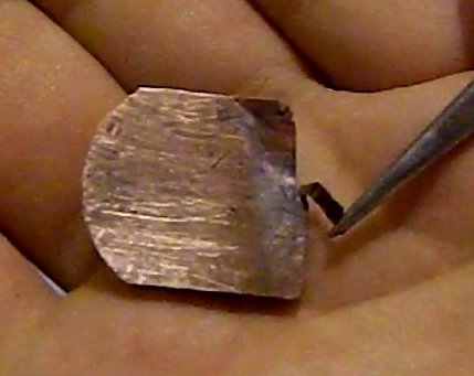
You can see that the water drops created some circular patterns in the copper oxides. The surface of the un-treated copper is ‘dotted’ or ‘noisy’ whilst the drop-sites are made of concentric rings. I only cleaned the left and centre of my sample before starting: ignore the mess you see on the right half.
(10) Gently brush away the upper surface of copper oxide using a tooth-brush. Avoid brushing away the dark, circular regions which lie under the surface layer as much as possible.
This is what the sample from above looked like after I brushed it:

These round, black regions are what we are after.
Testing and Results
I had succes with both pencils and lead-free solder as a contact against the round oxide regions. Although the photos show me using a rather large 5B pencil, similiar success was obtained with an ordinary pencil labelled as ‘dark’ (I didn’t have any HB at hand to try). Pressing a blunt pencil anywhere on the circular regions yielded curves that looked like these:
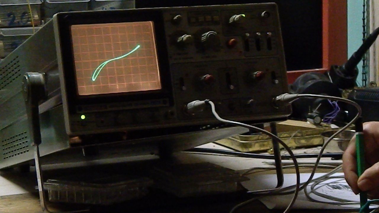
(vertical axis: 0.5V per division, horizontal axis: 1V per division)
I had to press very gently to get this result. When I pressed further the centre point on my oscilloscope (0V and 0A) screen would ‘twist’ away from being horizontal, suggesting I was putting a resistor in parallel with my junction. Pressing even further would cause the line to suddenly appear vertical (ie a short) until I released some pressure.
Conclusions
As mentioned in my opening paragraph: my junctions act like two diodes facing opposite directions in parallel (”antiparallel”). The reverse breakdown voltage is not that different to the forward breakdown voltage. This limits the usefulness of the diodes made by my exact method here to a few niche applications like distortion circuits and biasing. I really want to find a way of fixing this so that my diodes can be more practical.
I am not yet sure why there is an ‘open-looped’ region in my my I-V curves. My first thoughts were that I had created a memrister, however the scope probes I am using are not properly compensated and it might just be the effects of some capacitance. Although these tests were run at 50Hz (minimising the effects of the two afore-mentioned problems) I still want to test on another scope before I jump to any conclusions.
EDIT: Hmm, if it were capacitance then it should have affected the whole line, not just one half. Possibly some capacitance that gets shorted in the other half of the waveform?
The photos used in this article are from the second attempt at my method. I had hastily recorded the results of my first attempt on video just in case I was never able to repeat it again, but it seems this ‘water-drop’ method is somewhat reliable. I’ll only properly know when I get some more free time to try again.
I was wondering if it would be possible to make this type of diode directly on a copper-clad PCB. It would be interesting to try, however I would want to do it in a temperature-controlled fashion (and outdoors) to avoid my base material outgassing nastily. You could then deposit a mixture of mostly graphite powder (and perhaps a little glue or clay) to bridge between a copper track and a copper-oxide region. More things to experiment with!
I’m open to comments: add one anonymously below or shoot me an email (and say whether or not you want your comment published). Make sure to say something if you try my method, especially if it does not work for you!
Was hoping that you had continued your research. I believe it to important. I the event of an E.M.P. this my be the first component to restoring any type of storage power.
Hey Anthony,
Yes I'm continuing my work. Slowly, between other things. Make sure to checkout the other articles in the series too -- I'm focussing on the wet ionic technologies at the moment.
Not current written about on this site: I've developed kitchen-technology level ways of quickly 'masking' resistors, capacitors and diodes onto pieces of cardboard. The hard part is getting working transistors (without these very little computation can be done), I have a few ideas that I'm trying.
> I the event of an E.M.P. this my be the first component to restoring any type of storage power.
No, definitely not. If you are genuinely concerned about EM events then I recommend you read up more about the physics behind electro-magnetism (EM) and its interaction with our visible world. The worst thing to fear is the unknown.
In a nutshell: you cannot destroy most of the electronics on the planet unless you use EM levels high enough to kill most humans too. These levels of EM are impractically large, we're talking "hey the hills have turned into lava" amounts of power (and higher).
Small devices are less susceptible to EM than "big" devices. Humans are (relatively) not very big antennas, and old laptops/computers sitting disconnected in a pile somewhere are even smaller. Plus they're shielded by their metallic cases (laptops less so, long topic) which makes them harder to kill (look up "Faraday cages").
Big devices, or devices connected to long wires (power lines, phone lines, internet lines, etc) are more susceptible. The long wires act as antennas that funnel the EM into the devices. Exact results will vary depending on the power level of the EM event, the duration of the EM event, the frequency spectrum of the event and the exact devices+antennas themselves. Small EM events will be nuisances, big EM events will take out infrastructure and indirectly lead to loss of life. But old computers sitting under your bed will be fine if you are also fine.
To planet-wide deliver EM power levels & freq spectrum high enough to nuke all sizes of electronics (and therefore also humans) we'd need impractical amounts of energy. Have a look at the history of us trying to use EM to wirelessly power things, for example:
https://old.reddit.com/r/askscience/comments/15mcp7/how_is_wireless_power_transmission_possible/
(There's a lot to this topic. But the general gist is: multiple this by every square meter of the planet.)
EM events can be man-made or natural (eg solar events). The latter has happened before ( https://en.wikipedia.org/wiki/Solar_storm_of_1859 ) and as far as I know should not be strong enough to pose _direct_ threat to human life, so only some electronics will die. As far as man-made weapons go ("microwave weapons" or the fun imploding magnet EMP things) they still only affect specific targeted regions due to power limitations.
Questions, confusions or disagreement? I'm not perfect, expect errors, and I prefer it when people disagree.
Very interesting and old school. What do you envision a high voltage diode would look like for a neon sign transformer, using your method? I understand the losses would be great.
Hello Manhattan,
Problem 1: voltage handling. Water itself electrolyses as you increase the voltage, and from my tests + literature it seems to max blocking voltage of these devices tops out somewhere between 20V and 50V. You would need to make a lot and put them in series.
Problem 2: frequency handling. Can you run neon tubes at very low frequencies (eg 10Hz?) I don't think they'd be as easy to drive or efficient, but it's probably possible.
Doh! Wrong article. I thought this was the ionic diodes page. Please ignore my response Manhattan.
Copper diodes used to be used for large power rectification, and they used to stack them to get HV resistance. There's a few bits of information on the web about their historical usage. If you can make reliable ones then I don't see any problems trying to use them for neon signs.
... and I can't fix these comments because my host has changed rules again, preventing me from SSH'ing in. >:|
You should check out K7NS's ZnO diodes too... http://sparkbangbuzz.com/zinc-oxide-diode/zinc-oxide-diode.htm
Hey Peter Chubb,
Yes, it was pointed out to me in one of my other posts: https://halestrom.net/darksleep/blog/026_diode_array/#comments
Thankyou however. When I get a bit more free time I'll look into it again.
Easiest way to get pure zinc is to pull a heavy-duty battery apart. (Not an alkaline one, the caustic salts are too dangerous). I've been melting a small piece of zinc onto a small piece of the tinplate casing of a D-cell, and have created workable point-contact diodes. You need a hotter heat source than a candle; I've been using the side burner on my barbecue.
I've also been trying to reproduce your copper-oxide diode, using a 2c piece as the copper (it's 97% pure), and a spirit lamp rather than a candle; but no joy as yet. I thought I had something that worked, but the next day it didn't work any more.
Dangit, I need to publish my follow up & edit this article with some correction notes. The conclusions & hypothesis here are all wrong, I didn't perform good enough control tests.
It seems that using a weak point contact of graphite (eg pencil, pacer lead) onto most metals appears to provide similar double-diode dunctions, regardless of whether you have put the effort of forming a thick/specific oxide layer or not.
I've been using a copper cats whisker on ZnO2 with reasonable results. Copper catswhisker on Cu20 (BTW I thought originally that your water technnique was reducing Cu20 to Cu0) sort-of works. It's not really sharp though.
If you are looking for a homemade power rectifier, you could do what the old-timers did to charge their radio batteries from AC and make a electrochemical cell rectifier. A piece of aluminum and almost any other metal electrodes are submerged in a glass or other non-cunductive container of water with a little baking soda or sodium chloride disolved in it. These electrodes must not touch each other.
A conductor is clipped to each electrode. An incanescent lamp is wired in series with this arrangement (one of the lamp contacts hooked up to one of the electrode wires with a return wire connected to the other lamp contact) and an AC voltage applied between the remaining electrode wire and the lamp return wire. When the lamp drops to about half brightness, the rectifier has formed. The lamp may be set aside since it is not needed anymore.
If the rectifier you made is stored for an extended period it may need to be reformed as before. The water solution will also need to be topped up occasionally as it evaporates during use.
Just make sure you know what you are doing when working with liquids and electricity so you don't get electrocuted.